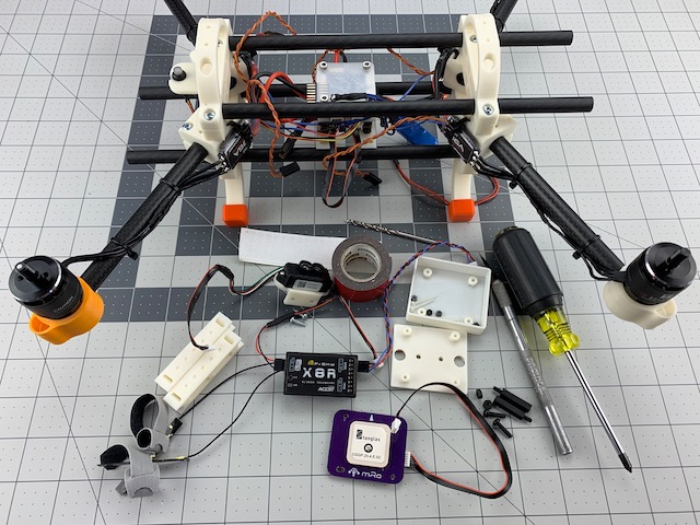
Receiver, GPS, and Sensors
In this step we will install the RC receiver, GPS module and LiDAR sensor. We have chosen our sensors for this build based on a mix of size, capabilities and support. Any ArduPilot compatible GPS/compass module will work. You also need to choose a receiver for your particular brand of radio. We really like FrSky for it’s pass-through telemetry support in ArduPilot. The TFMini LiDAR is optional, but we like the better precision it offers in flight modes that can leverage the data. Just remember, the parameter file we will include in a later step will be specific to these sensors, so adapt as required.
Caution – This section requires soldering. A bad solder joint can cause complete loss of power so please make sure you are comfortable creating good solder joints before proceeding.
What You Need (BOM)
The following should be everything you need to install the Receiver, GPS and TFMini LiDAR.
Printed Parts
| Qty | Part | Notes |
|---|---|---|
| 1 | Cross Mount | Receiver |
| 1 | mRo GPS Mount | Per choice of GPS |
| 1 | mRo GPS Cover | Optional |
| 1 | Benewake TFMini Mount Angle |
Electronics
| Qty | Part | Notes |
|---|---|---|
| 1 | mRo M8N GPS | w/ compass |
| 1 | FrSky X8R Receiver | w/ PCB antennas |
| 1 | Benewake TFMini LiDAR | Serial |
Cables
| Qty | Part | Notes |
|---|---|---|
| 1 | 6 Pins JST-GH to 6 Pins JST-GH | GPS |
| 1 | 6 Pins JST-GH to 4 Pins JST-GH | TFMini, Custom soldered for serial connection |
| 1 | 3 Pin Servo (SPort) to 4 Pin JST-GH | FrSky Telemetry |
| 1 | 3 Pin Servo (SBus) to 5 Pin JST-GH | RC In |
Fasteners
| Qty | Part | Notes |
|---|---|---|
| 2 | #4 x 3/8in Pan Head Screw | TFMini mount, Phillips drive |
| 2 | #2 x 3/8in Pan Head Scrw | TFMini, Phillips drive |
| 2 | M3 x 12mm Pan Head Screw, Nylon | GPS mount |
| 4 | M2 x 20mm Pan Head Screw, Nylon | GPS cover |
| 4 | M2 Nut, Nylon | GPS Cover |
| 2 | M3 Nut, Nylon | GPS Mount Standoffs |
Standoffs
| Qty | Part | Notes |
|---|---|---|
| 2 | M3 x 20mm, Male-Female, Nylon | GPS mounting |
Tools
- #1 Phillips screw driver
- Knife
- 3mm drill bit
- Drill
Misc
- Double-sided Tape
- Velcro (sticky back)
- (2) Zip Ties
- (2) 1/4in x ~1in Heat Shrink Tube
- PixRacer Pinout
- TF Mini Pinout
Caution – Before proceeding please make sure you are familiar with your flight controller and sensor port pinouts. Incorrect wiring can cause systems failures and damage to hardware.
Step 1 - Install Receiver
In this step we will install the FrSky X8R reciever and connect it to flight controller. You will need:
- FrSky X8R Receiver w/ cables
- (1) Cross Mount
- Velcro (sticky back)
- (2) Zip Ties
- (2) 1/4in x ~1in heat shrink tube
- Wire Cutters
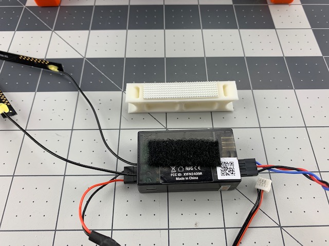
1.1 Install Velcro
- We are using velcro to mount the reciever so we can more easily remove it for maintenance/binding etc.
- Install loop on back of receiver
- Install hook on top of Cross Mount
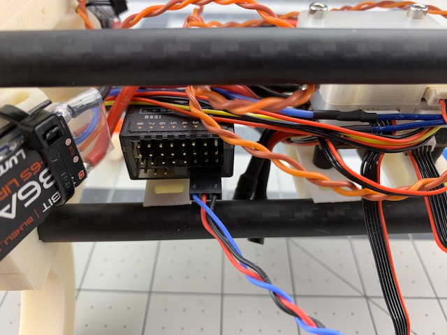
1.2 Install Receiver
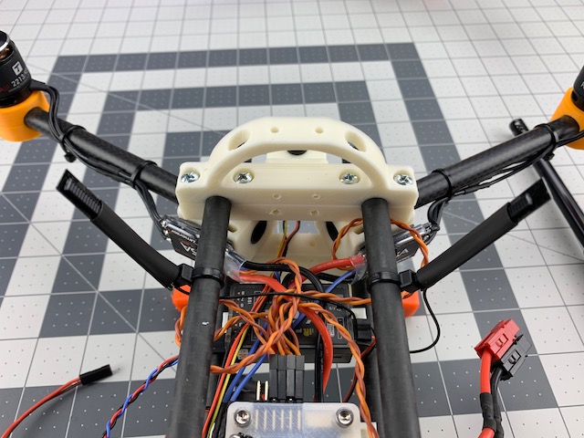
- Install the Cross Mount behind the PDB/flight controller stack on the two bottom frame tubes.
- Carefully place the receiver on the Cross Mount and push down to mate the velcro.
- Per the PixRacer Pinout route the sPort wire from the reciever to FrSky port on the PixRacer.
- Per the PixRacer Pinout route the SBUS out from the receiver to the RC IN/SBUS port on the PixRacer.
1.3 Install Receiver Antennas
- We like to keep the antennas in a good position to help maintain signal strength, and keep them out of the props. So we will use two zip ties to act as antenna mounts.
- Wrap a zip tie around one of the top frame tubes directly above receiver.
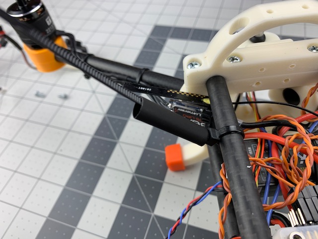
- Place heat shrink tube over the tag end of the zip tie as shown above.
- Insert one of the receiver’s PCB antennas into the heat shrink tubing and carefully shrink the tube until snug around the antenna.
- Repeat for other side and antenna.
- Carefully trim the tag end of zip tie.
- Rotate the zip ties/antennas so they are pointing about 45 degrees outboard.
Step 2 - Install GPS
In this step we will install the mRo GPS module. Note that we are using all nylon fasteners in this step to avoid causing interference with the GPS and compass. Anything non-ferrous will work. You will need:
- mRo GPS Module
- mRo GPS Mount
- mRo GPS Cover
- (2) M3 x 20mm, Male-Female, Nylon Standoffs
- (2) M3 Nut, Nylon
- (2) M3 x 12mm Pan Head Screw, Nylon
- (4) M2 x 20mm Pan Head Screw, Nylon
- (4) M2 Nut, Nylon
- PixRacer Pinout
Caution – Improper mounting/connection of the GPS and compass module can cause unpredictable position and heading errors that may lead to erratic behavior and/or fly aways.
2.1 Install GPS Mount
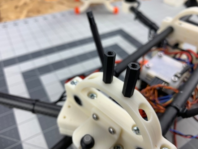
- We will start by installing the nylon M3 standoffs. These will provide some seperation to clear our battery and reduce potential impacts from interference caused by motors and ESC’s.
- Use the 3mm drill bit to clear out the two mounting holes on top of the rear Box End Roll Cage.
- Insert the male end of the M3 x 20mm standoff into the Roll Cage mounting hole and secure with an M3 nut.
- Repeat one more time.
Note – We are about to install the GPS Mount and Cover, so make sure the holes in the mount and cover are large enough for fasteners. Due to printing tolerances they are likely too small straight off the printer. Drill out, dry fit and adjust before you proceed.
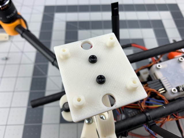
- Line up the mRo GPS Mount mounting holes over the two standoffs you just installed.
- Secure the GPS Mount with (2) M3 x 12mm nylon pan head screws
2.2 Install GPS
- Line up mRo GPS Module over four mounting holes in GPS Mount. Pay attention to proper module orientation.
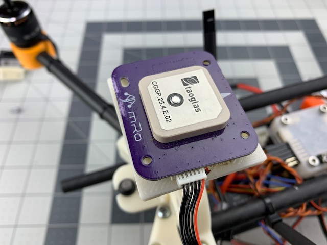
- Per the PixRacer Pinout connect the GPS Module to the PixRacer GPS port using a 6 Pin to 6 Pin JST-GH cable.
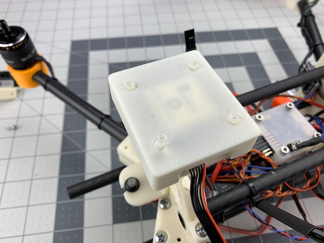
2.3 Install GPS Cover
- Place GPS Cover over GPS Module and Mount
- Secure GPS Cover with (4) M2 x 20mm Pan Head Screws and Nuts. You may trim the ends of these screws once installed.
Step 3 - Install LiDAR
In this step we will install and connect the Benewake TFMini LiDAR. You will need:
- TFMini w/ cable
- TFMini Mount Angle
- (2) #2 x 3/8in Pan Head Screw
- (2) #4 x 3/8in Pan Head Screw
- #1 Phillips Screw Driver
- PixRacer Pinout
- TF Mini Pinout
Note – Before proceeding you will need to reference the TF Mini Pinout to build a 6 Pin JST-GH to 4 Pin JST-GH cable.
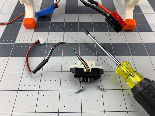
3.1 Mount TFMini
- Use (2) #2 x 3/8in pan head screws to attach the TFMini module to the TFMini Mount.
3.2 Install TFMini
- Use (2) #4 x 3/8in pan head screws to attach the TFMini Mount to the rear box end. See image below for mounting location.
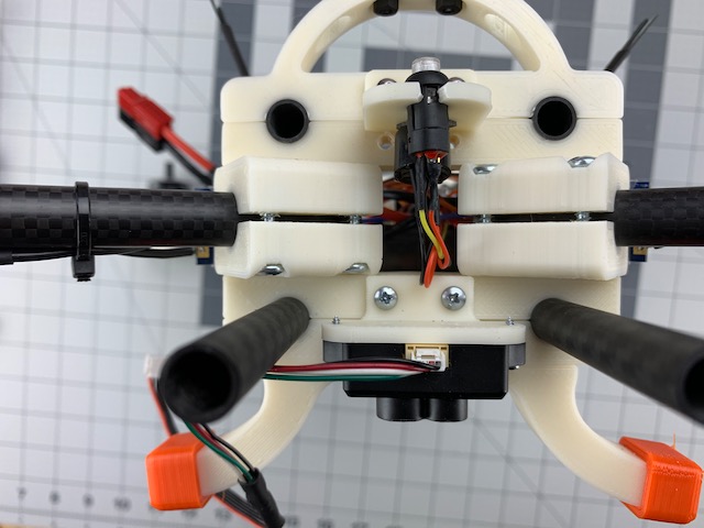
- Per the PixRacer Pinout connect the TFMini cable to the Telem1 port of the PixRacer
Great job! Next we will install the mounts for the battery and secure the 5V BEC.