Flight Controller
Note – An important factor in choosing a flight controller for your project is the number and types of ports supported by the board. In particular, ensure that your flight controller has enough serial ports to support all sensor and telemetry connections.
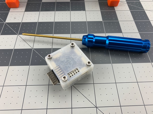
In this step we will install the flight controller with safety switch. We have chosen to use the PixRacer for this build as we like the mix of size, capabilities and support. Any ArduPilot compatible flight controller with right number and types of ports will work. Just remember, the parameter file we will include in a later step will be specific to the PixRacer, so adapt as required.
What You Need (BOM)
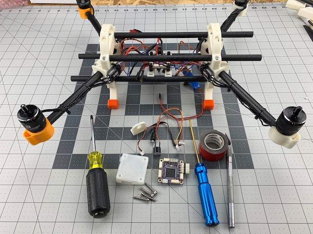
The following should be everything you need to install the flight controller and safety switch.
Printed Parts
| Qty | Part | Notes |
|---|---|---|
| 1 | Switch Mount Angle | Accessory Mounts » Generic |
Flight Controller
| Qty | Part | Notes |
|---|---|---|
| 1 | Pixracer | With case |
| 1 | Safety Switch | With buzzer |
Fasteners
| Qty | Part | Notes |
|---|---|---|
| 4 | M3 x 20 Machine Screw | PixRacer, Phillips or hex drive |
| 2 | #4 x 3/8in Panhead Screw | TFMini mount, Phillips drive |
Cables
| Qty | Part | Notes |
|---|---|---|
| 1 | 6 Pins JST-GH to 6 Pins JST-GH | Power, current/voltage sense w/ buzzer |
Tools
- 2.5mm hex driver (if you use hex drive for flight control mounting)
- #1 Phillips screw driver
- Knife
- 3mm drill bit (if you need to make bigger mounting holes in your PixRacer case)
- Drill
- Wire cutters
Misc
- Double-sided Tape
- PixRacer Pinout
- Motor Order Diagram
Caution – Before proceeding please make sure you are familiar with your flight controller and sensor port pinouts. Incorrect wiring can cause systems failures and damage to hardware.
Step 1 - Flight Controller
We are going to attach the flight controller to PDB stack from the last step, and plug into PDB. You will need:
- PixRacer w/ case
- (4) M3 x 20mm screws
- Power Cable (6P JST-GH to 6P JST-GH)
- PixRacer Pinout
- Motor Order Diagram
Note – We modified the stock mRo PixRacer case by drilling out the four corner mounting holes with a 3mm drill bit. This allows us to use M3 screws to attach through the case and into PDB stack.
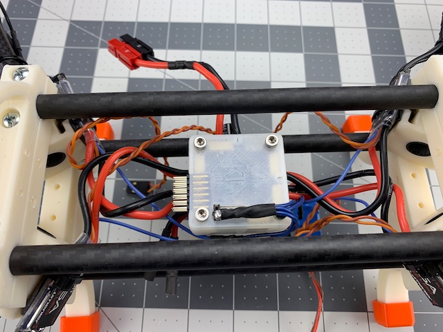
1.1 Mount Flight Controller
- Place four M3 x 20mm screws through each mountng hole in PixRacer Case
- Line up screws over the nylon standoffs on PDB stack
- Tighten screws to secure
1.2 ESC Telemetry Connection
- Per the PixRacer Pinout plug in ESC Telemetry wire as shown above.
1.3 Flight Control Power
- Per the PixRacer Pinout plug in one end of 6P JST-GH cable to PDB and other end to flight control power port. We will clean up our wiring harness in a later step, so for now you can leave it loose.
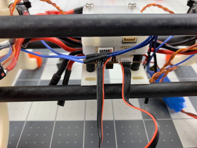
1.4 ESC Signal Connection
- Per the PixRacer Pinout plug in the ESC signal wires to the PixRacer motor outputs using the Motor Order Diagram as a guide.
Step 2 - Safety Switch
In this step we will install the safety switch and buzzer on the rear box end. You will need:
- Safety Switch with Buzzer
- Switch Mount Angle
- (2) #4 x 3/8in pan head screws
- Wire cutters
- #1 Phillips screw driver
- Per the PixRacer Pinout
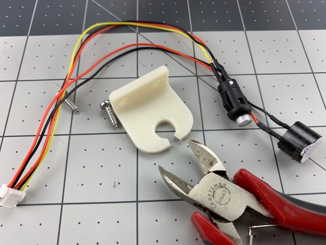
2.1 Prep Safety Switch Mount
- Use the wire cutters to carefully create a slot in the Switch Mount as shown in the picture above. This will allow for the wire harness of the switch and buzzer to be routed as needed.
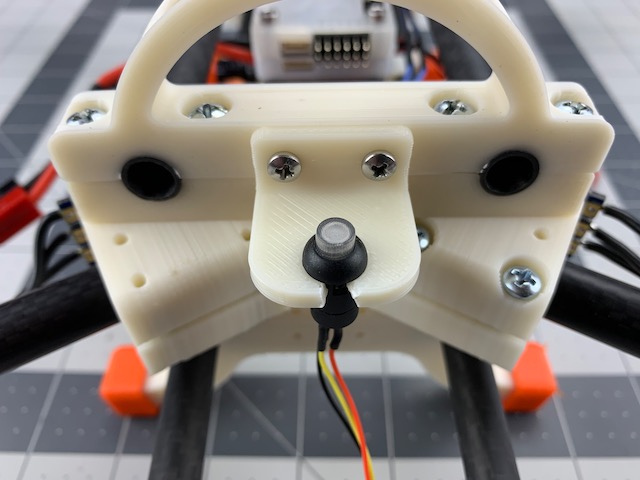
2.2 Mount Safety Switch
- Align the Switch Mount Angle to the two mounting holes in the rear box end of the frame as shown in image below.
- Fasten the mount with the two #4 x 3/8in screws. Do not overtighten.
- Insert the safety switch into the hole of the Switch Mount.
2.3 Mount Buzzer
- Cut and secure a small peice of double-sided tape to the top of the buzzer.
- Carefully align and press the tape and buzzer to the bottom of the Switch Mount as shown in image below.
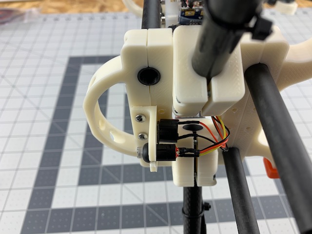
- Route the wires and plug into the flight control switch/buzzer port.
Nice job! This step is complete. In the next steps we will install the rest of our gear. We will secure our wiring harness after we know everything works as it should.