Basic Frame
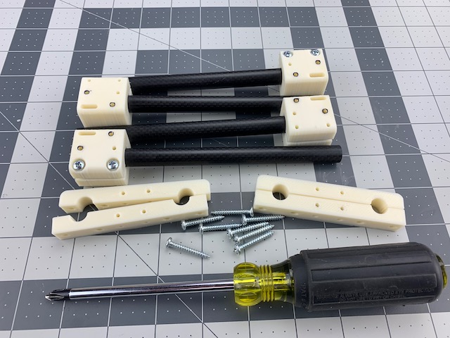
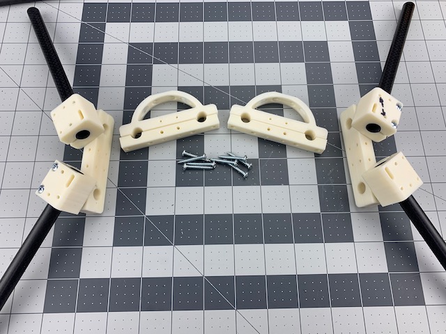
In this section we will turn this pile of parts…
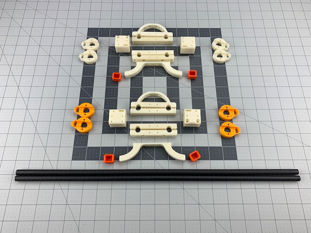
Into this base frame asssembly…
What You Need (BOM)
The following should be everything you need to build the base frame.
Printed Parts, ABS
| Qty | Part | Notes |
|---|---|---|
| 2 | Box End Roll Cage | |
| 2 | Box End Rounded | |
| 4 | Box End Square | |
| 4 | Arm Tube Mount 12mm | |
| 2 | Landing Gear | |
| 4 | Landing Gear Caps | Optional |
Pan Head Screws (aka Sheet Metal and Self Tapping)
| Qty | Size | Note |
|---|---|---|
| 16 | #6 x 1in (M3.5 x 25mm) | Box Ends |
| 8 | #6 x 3/4in (M3.5 x 20mm) | Arm Tube Mounts |
| 4 | #4 x 1/2in (M3 x 12mm) | Landing Gear |
Carbon Fiber Tube, Roll Wrapped
| Qty | Size | Note |
|---|---|---|
| 2 | 10mm OD x 500mm long | Supports 9in props and ~5000mAHr 3S lipo |
| 2 | 12mm OD x 500mm long | Supports 9in props |
Note – Length of tube can vary depending on design intent. Above figures are for standard stretch X config. If this is your first devFrame build we suggest building per docs. You can tweak it later.
Tools
- Ruler
- Marker
- Masking tape (optional)
- Hacksaw or rotary tool with cutoff wheel
- #1 and #2 Phillips screwdriver
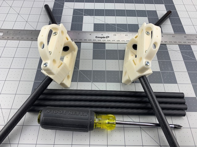
Step 1 - Cut Tubes
 In this step we will measure, mark and cut the carbon fiber tubes for both the box frame and arms. You will need:
- (2) 10mm x 500mm Carbon Fiber Tube (or enough to get (4) x 250mm tubes)
- (2) 12mm x 500mm Carbon Fiber Tube (or enough to get (4) x 170mm tubes)
- Ruler
- Marker
- Masking tape (optional but makes this step easier)
- Hacksaw, or rotary tool with cutoff wheel
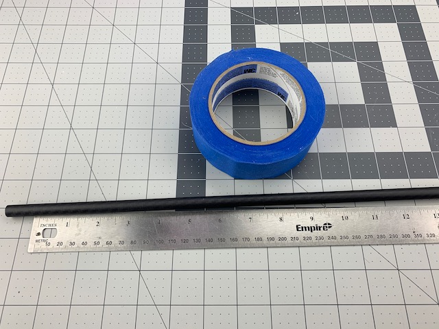
1.1 Measure and Mark Tubes
1.1.1 10mm Tube
- We will create four lengths of 10mm tube at 250mm length
- If you have two 500mm lengths of 10mm tube you are essentially cutting them in half
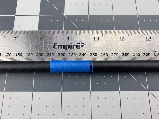
- Use ruler to measure 250mm length
- To help make a clean cut you can use tape to wrap at 250mm
- Otherwise, use marker to mark tubes at 250mm
1.1.2 12mm Tube
- We will create four lengths of 12mm tube at 170mm length. These tubes can be up to 190mm length if you would like to run 10in props.
- Use ruler to measure 170mm length
- To help make a clean cut you can use tape to wrap tube at 170mm
- Otherwise, use marker to mark tubes at 170mm
1.2 Cut Tubes To Length
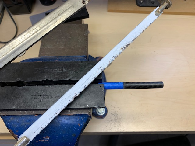 Using a hacksaw or rotary tool with cutoff wheel cut the tubes to the marked lengths. Take your time and rotate the tube as you make the cut.
Note – Don’t forget safety glasses and a dust mask. And carefully clean up any dust created. A damp rag works well on carbon dust.
1.3 Tubes Complete
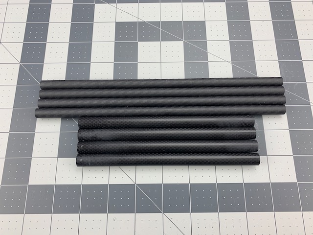 At the end of this step you should have eight total tubes:
- (4) 10mm x 250mm
- (4) 12mm x 170mm
Step 2 - Assemble Arm Tube Mounts
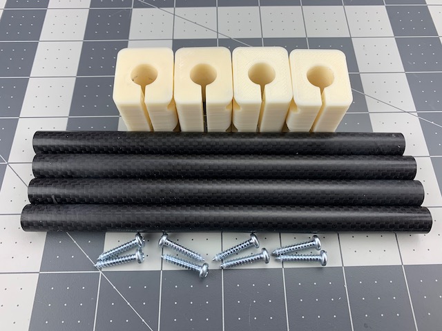 In this step we will join the arms tubes and Arm Tube Mounts. You will need:
- (4) 12mm x 170mm Carbon Fiber Arm Tubes
- (4) Arm Tube Mounts
- (8) #6 x 3/4in Pan Head Screws
- #2 Phillips screwdriver
2.1 Clamp Arm Tube Mounts
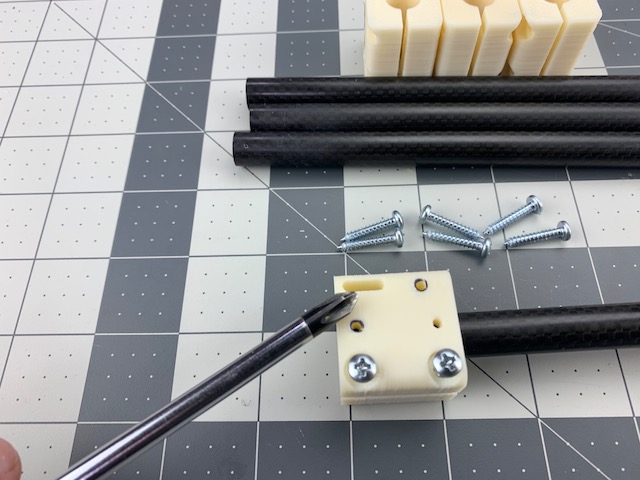
- We will assemble these one at a time.
- Insert a 12mm carbon fiber arm tube into an Arm Tube Mount.
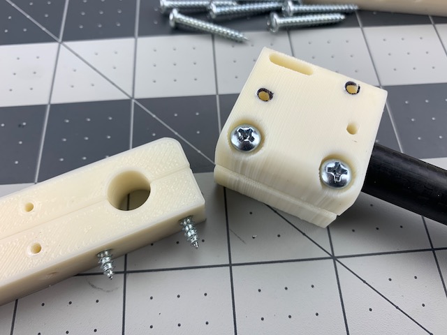
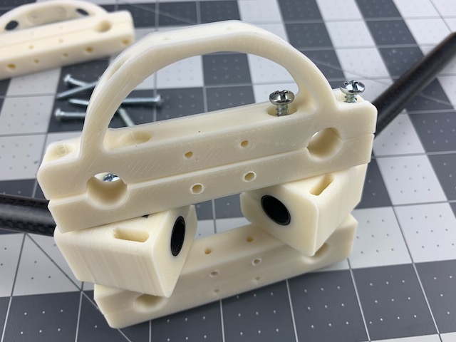
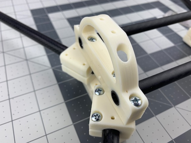
- Noting orientation of tube and mount, insert the tube until it is flush on the end of the mount. The screwdriver is pointing at the ziptie slot which should always be on the inside when the tubes are installed.
Note - Do not overtighten the screws in the frame or you could cause the parts to strip or crack. After installing a few you will get a feel for how much force is required. Take your time.
- Use (2) #6 x 3/4in pan head screws to clamp the tube in place.
- Repeat three more times.
2.2 Arm Tube Mounts Complete
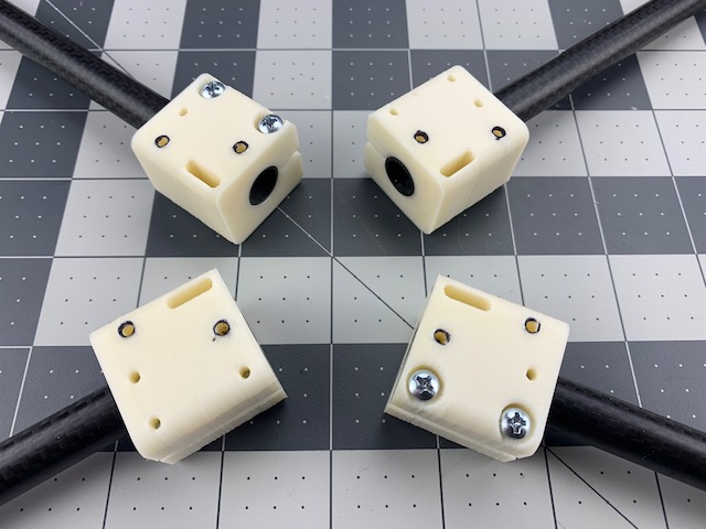 At the end of this step you should have four Arm Tube Mounts with arm tubes clamped.
Note - The Arm Tube Mounts are identical for all arms. This means when you assemble them to the Box Ends you will need to rotate them so that two have screw heads up and two have screw heads down. See image above. Note how ziptie slots are always to inside.
Step 3 - Assemble Box Ends
 In this step we will assemble the box ends. You will need:
- (4) Arm Tube Assemblies (the parts from last step)
- (2) Box End Round
- (4) Box End Square
- (2) Box End Roll Cage
- (16) #6 x 1in Pan Head Screw
- Ruler
- #2 Phillips screwdriver
Note – Do not fully tigthen screws in this step. We will tighten them in Step 4 when we install the frame tubes.
3.1 Box End Bottom
 We will start on the bottom of the Box Ends. Remember, we are on the bottom so are working upside down for now.
- We will do this one set and arm at a time.
- Match and align holes on a Box End Square and Box End Rounded.
- Place a #6 x 1in screw through each of the two holes as pictured.
- Align screws with the two holes on an Arm Tube Assembly (one of the parts from last step).
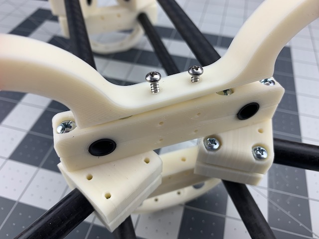
Note – The devFrame can support different arm geometries so there is an extra hole in the Arm Tube Mount. We used a black marker on the desired holes for this build, which will give us 30 deg arm sweep. See image above.
- With the holes in the Arm Tube Mount and screws from the Box End Bottom aligned, start, but do NOT completely tighten, the screws. Engage just enough threads to hold our assemblies together.
- Repeat for opposite end of Box End Bottom. Pay attention to orientation of each arm. We want a stretch X, not another letter of the alphabet.
- Repeat entire step for opposite Box End.
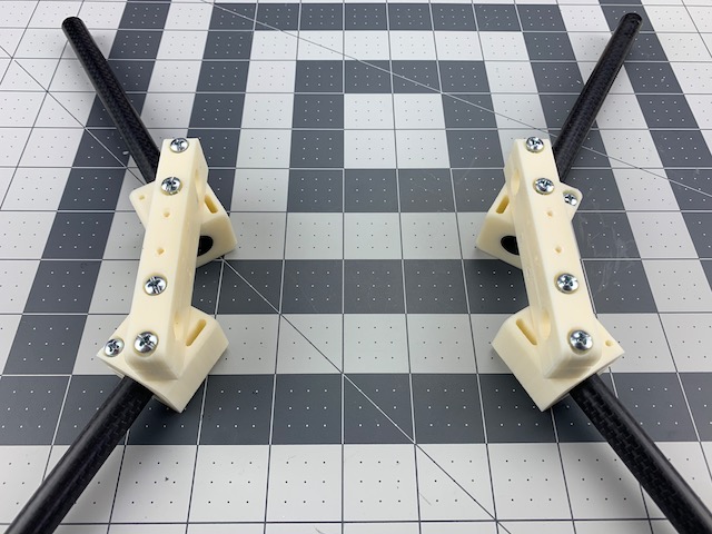 You should now have two assemblies as pictured above.
3.2 Box End Top
 In this step we are going to assemble and attach the top parts of the Box Ends.
- We will do this step one end at a time
- Flip over one of your assemblies from the last step so it is right side up.
- Align holes of a Box End Roll Cage and Box End Square.
- Place a #6 x 1in screw through each of the two holes as pictured.
- With the holes in the Arm Tube Mount and screws from the Box End Top aligned, start, but do NOT completely tighten, the screws. Engage just enough threads to hold our assemblies together.
- Repeat for opposite end of Box End Top.
- Repeat entire step for opposite Box End.
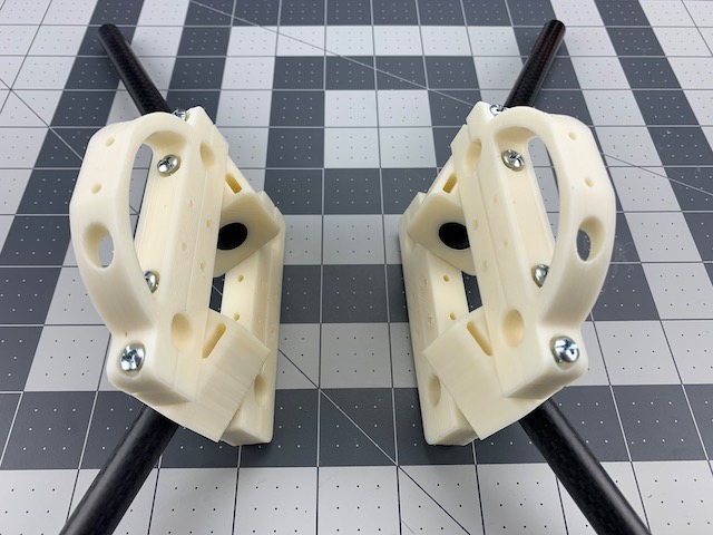 You should now have two assemblies that look like the ones pictured above. We are almost there.
Step 4 - Install Box Tubes
 In this step we will clamp the 10mm frame tubes to the Box Ends. If you fully tightened the screws from the previous Box End steps go ahead and loosen them up. Told you. We’ll wait. You will need:
- (2) Box End Assemblies (parts from last step)
- (4) 10mm x 250mm Carbon Fiber Tubes
- #2 Phillips screwdriver
- Ruler
Note – The clamps are designed with enough surface area to self-align the tubes to an extent, but it helps if you build on a nice flat bench to ensure the frame is true and square while you tighten fasteners.
Note – We have chosen to leave the frame tubes long so they will extend beyond the Box Ends. This helps avoid wasting tube, and provides extra space to hang more gear. We suggest building as documented in this section before you decide whether to modify tube length.
4.1 Box End Top
- We will start on the top/rear and then move to top/front. So, time to pick a front and rear Box End.
- At this point there is really no difference in the assemblies, but we will install tubes with staggered overhang, so pick one to be a Box End Rear.
- Place (2) 10mm tubes into the Box End Rear Assembly as pictured above.
- Align the end of the tubes so they are flush with the outside of the Box End Rear.
- Slowly tighten the top screws of the Box End Rear to engage the clamps. Again, if you get it wrong just loosen and do it again. No worries. Unless you over tighten.
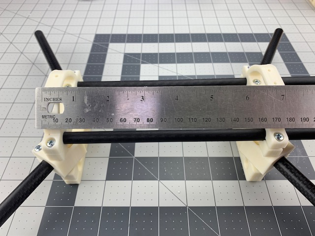
- Slide the Box End Front on the two tubes you clamped to the Box End Rear in the last step.
- Use the ruler to measure about 180mm from outside to outside of the Box End Assemblies. See photo.
- Once in place you can slowly tighten the top screws of the Box End Front to engage the clamps.
4.2 Box End Bottom
- Roll the entire assembly over and repeat for bottom frame tubes.
Note – We build this with extra top tube length extending out the front and bottom tubes sticking out the rear. This is to provide extra room to mount gear beyond both front and rear box ends. You can change this later if desired.
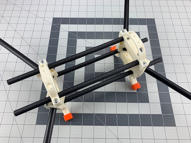
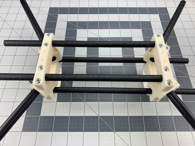 When you are done with this step you should have a nearly complete base frame as pictured (Yes, it’s upside down. For next step.)
Step 5 - Install Landing Gear
 In this step we will install the Landing Gear. They are optional if you do not need the ground clearance, but we have found them to be very good at keeping wet grass out of electronics and sensors. You will need:
- Base Frame Assembly from last step
- (2) Landing Gear
- (4) Landing Gear Cap TPU (optional, but really help make it bounce better)
- (4) #4 x 1/2in Pan Head Screw
- #1 Phillips screwdriver
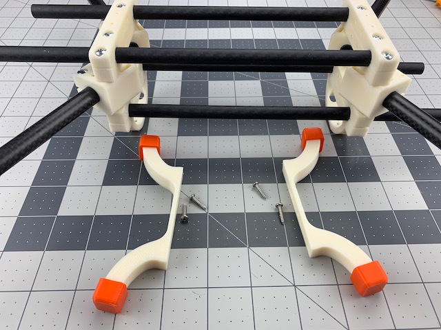
- We will do this one end at a time. Make sure your Base Frame is upside down.
- Place a #4 x 1/2in screw through each of the two holes on a Landing Gear
- Align the screws with the holes in the bottom a Box End. Either one.
- Tighten the screws.
- Repeat for other Box End and Landing Gear.
- Flip it over and admire your work!
Base Frame Complete
Congrats! Grab your favorite beverage and admire your work. You have just built a base frame. The really cool thing is building another size or config is the same. Just change the length of tubes and/or arm angle as required. In the next section we will start loading it up with gear.