Power, Motors, ESC’s
Caution – This section requires soldering. A bad solder joint can cause complete loss of power so please make sure you are comfortable creating good solder joints before proceeding.
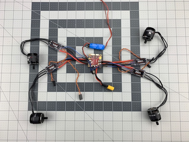
In this section we will install power distribution, motors, and electronic speed controls (ESC’s).
Note – One of the more challenging aspects of building your own robot is providing clean power to various components with different voltage and current demands. Make sure you consider all power requirements for your use case.
There are many different types and brands of equipment that can meet your onboard and flight power needs. We are using what we had available in the shop, as well as what we feel represents a general 450 class setup.
What You Need (BOM)
Besides the base frame from the last section, the following should be everything you need to install power distribution, motors and ESC’s.
Printed Parts
| Qty | Part | Notes |
|---|---|---|
| 8 | Motor Mount Half 12mm | |
| 2 | Cross Mount |
Fasteners
| Qty | Size | Note |
|---|---|---|
| 8 | M3 x 22mm Machine Screw | Motor Mounts, Phillips or hex drive |
Standoffs
| Qty | Size | Note |
|---|---|---|
| 4 | M3 x 6mm | Vibration Isolation |
| 4 | M3 Hex Nut |
Power Distribution
| Qty | Size | Note |
|---|---|---|
| 1 | MRo ACSP4 Power Module | Or equivalent |
| 1 | Castle Creations 10A BEC | Or equivalent |
Flight Power
| Qty | Size | Note |
|---|---|---|
| 4 | T Motor 2213/920KV Motors | Or equivalent |
| 4 | Luminier 36A BLHeli32 ESC | Or equivalent |
Wire and Connectors
| Qty | Size | Note |
|---|---|---|
| 1ft | 12-14 AWG Silicone Wire | Battery to PDB |
| 1ft | 16 AWG Silicone Wire | Optional - depends on motors and ESC’s |
| 2 pair | Anderson Power Poles 45A | XT80 or equivalent |
Misc
- Small zipties
- Double sided tape
- Heat Shrink Tube
- (2) 0.1in Single Row Header Pins - Optional; depends on ESC telemetry connection
Tools
- #1 and #2 Phillips screwdriver
- Needle Nose Pliers
- Wire Cutters
- Wire Strippers
- Soldering Kit
Step 1 - Power System Wiring
Note – The motor mounts are designed to support routing the wires inside the arm tube. In this build we will route outside the tube. It is largely a matter of preference. Routing motor wires outside the arm tube is slightly easier to assemble and maintain, while routing inside the tube presents a cleaner build.
In this step we will connect wires between motors and ESC’s, between ESC’s and PDB, connect our battery leads, and add a 5V BEC. You will need:
- Motors
- ESC’s
- PDB
- BEC (and any other equipmet soldered to PDB)
- Ruler
- Wire Cutter
- Wire Strippers
- Soldering Kit
- Heat Shrink Tubing
- Wire (if not supplied with motors or ESC’s)
1.1 Motors to ESC’s
-
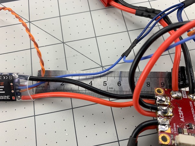
To get accurate measurements, first locate mounting position for the ESC’s. We will install our ESC’s for this build on the Arm Tube clamps using double-sided tape and zip ties.
-
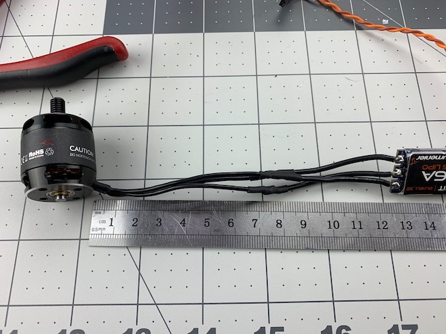
Measure and note distance between motors and ESC’s. Add a few millimeters to allow for overlapping solder joints.
- Solder each motor wire to ESC wire.
- Repeat three more times until all motor to ESC wires are soldered.
1.2 ESC’s to PDB
- We will be mounting the PDB under the flight controller in the middle of the bottom set of frame tubes.
- Measure and note distance between ESC’s and PDB. Add a few millimeters to allow for overlappig solder joints.
- Solder each ESC wire to PDB
- Repeat three more times until all ESC wires are soldered to PDB
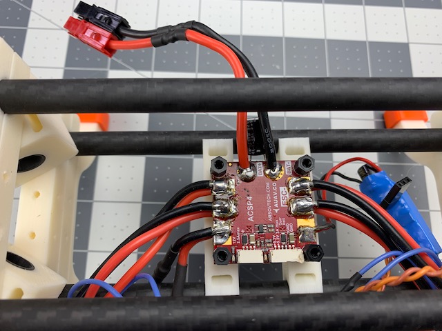
1.3 Battery and BEC Connections
- In Step 2 we will physically install the PDB to the frame, which will limit access without removing, so now is a good time to solder any other wires needed for your build.
- We soldered 12AWG silicone wire to our battery connections. We recommend leaving these wires long if you are not sure how your battery will mount. We plan on mounting our battery to the top level of the frame so know our approximate wire length.
- Now is also a good time to solder on any extra connections to PDB. We installed a 5V BEC to provide power to equipment such as companion computer and high power demand sensors.
1.4 ESC Telemetry Wires
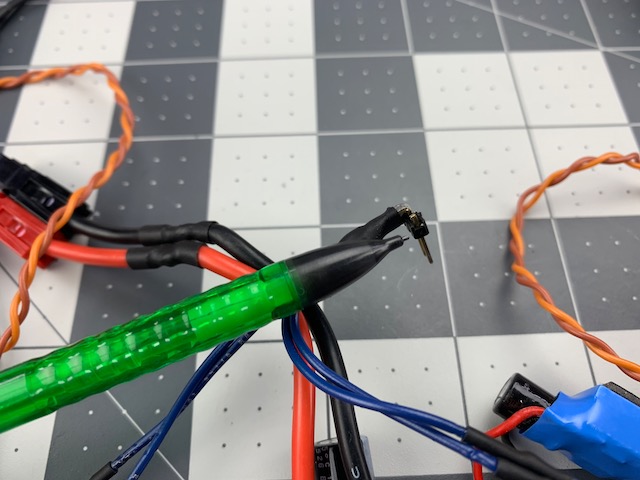
- We plan on using ESC telemetry for this build, which requires soldering each of the ESC telemetry wires together.
- The telemetry wire bundle needs to be connected to a serial port on the flight controller. You will need to solder the telemetry wires to a harness/connector supported by your choice of autopilot.
- We will use the WiFi module port on the top of the PixRacer. As that port accepts 0.1in Dupont pins we will solder our ESC telemetry wires to a header pin. We actually use two pins, but one is blank to help keep the connection more secure.
Once you are done you should have a power system ready to be installed.
Step 2 - Install Power System
In this step we will install the power system from the last step onto the base frame. You will need:
- Base Frame Assembly
- Power System
- (2) Cross Mounts
- (4) M3 Anti-vibration Standoffs with M3 nuts
- (4) Nylon Standoffs
- (8) Motor Mount halves
- (8) M3 x 22mm Screws
- Double Sided Tape
- (12) Zip Ties
- Drill
- 3mm Drill Bit
- Needle Nose Pliers (or very small wrench)
- #1 Phillips Screwdriver
- Wire Cutters
- Knife
2.1 Install Cross Mounts
- First, we will install two cross mounts on the lower two frame tubes.
- The Cross Mounts have index holes but we need some through holes to mount the standoffs. So we will need a drill.
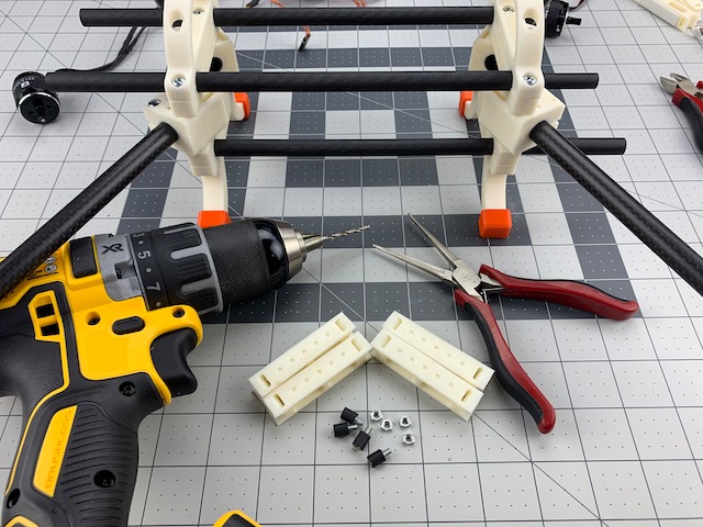
- The outside pilot holes on the Cross Mounts are spaced 30mm. Close enough to 30.5mm to mount the PDB. Drill out the pilot holes - on the top layer only - with a 3mm drill bit. We marked them with a black marker in the image below.
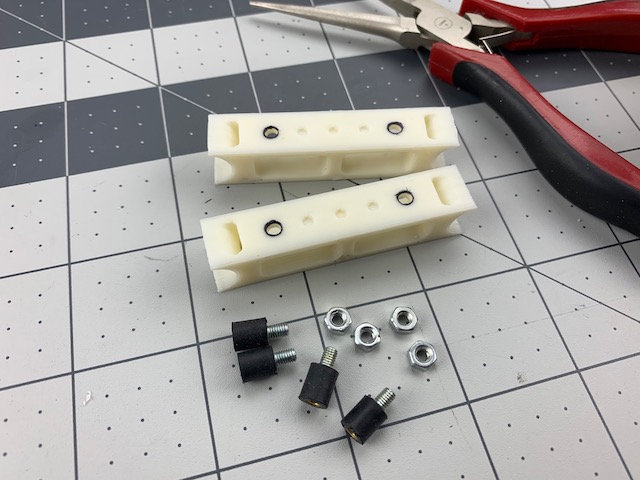
-
Insert the threaded end of a standoff and secure with an M3 nut. There is just enough tool clearance for needle nose to help tighten the nut.
-
Repeat three more times.
-
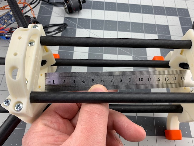
Install Cross Mounts across the bottom tubes. Insert them at an angle and twist until they snap into place. Slide them to about center and spaced 30mm apart.
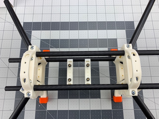
2.2 Install PDB
- Use the PDB to align the Cross Mounts and standoffs.
- Use the four nylon standoffs to attach the PDB to the anti-vibration standoffs
Note – There are many ways to mount PDB’s and flight controllers. The intent here is to provide some vibration isolation, orient the PDB for easiest access to wiring, and provide a stable mount for flight control. Choose the method that works best for your use case and supply chain.
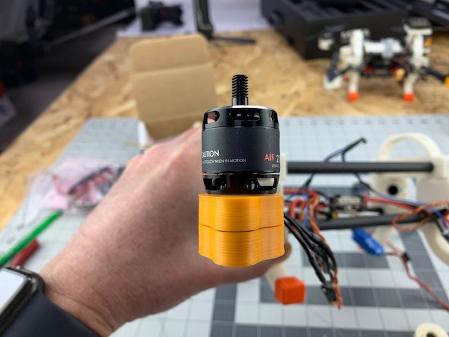
2.3 Install Motors
Note – Now is a good time to route your ESC’s and Motors to respective arms. If you have a motor and prop system that uses left and right hand threads make sure you pay attention to prop rotation.
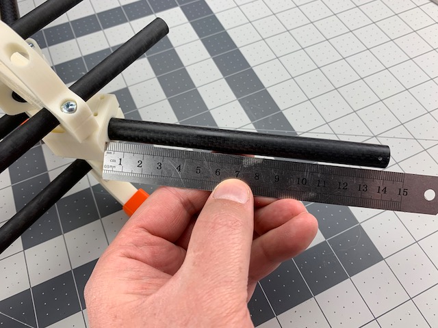
- Now we willl mount the motors to the end of the arm tubes.
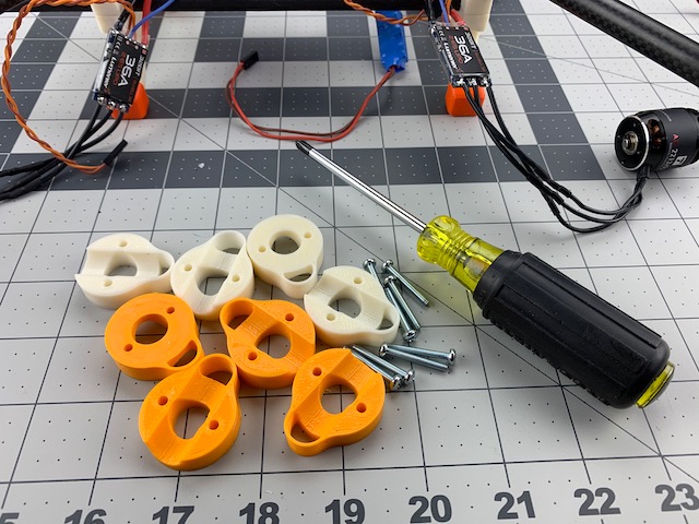
- Take two of the Motor Mount Halves and insert two motor mount screws.
- Slide onto end of an arm tube until you can see end of tube through opening in motor mount wire protectors.
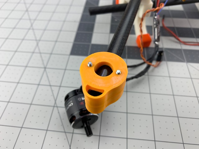
- Align the two 19mm spaced holes on bottom of your motor with the ends of the two screws.
- Tighten until the motor will just hold in place on it’s own but still allow alignment.
- Sight down the motor/motor mount assembly to the frame and make sure the motor can is vertical to frame tubes. Visually aligning the bottom of motor mount with bottom of arm tube mount works well to get started. Then verify motor can is aligned as well.
- Slowly tighten each motor mount screw in an alternating pattern until full clamping force is achieved.
- Repeat until all motors are mounted and aligned.
Caution – The motor mounts use clamping force and are not otherwise indexed to frame. We have found that this works well in normal use, but in case of hard impacts and/or crashes the motors may twist on the tubes. While this helps to avoid transferring some stress to the frame during impact, it can also cause thrust misalignment and severe flight issues if not corrected. ALWAYS check motor alignment prior to flight.
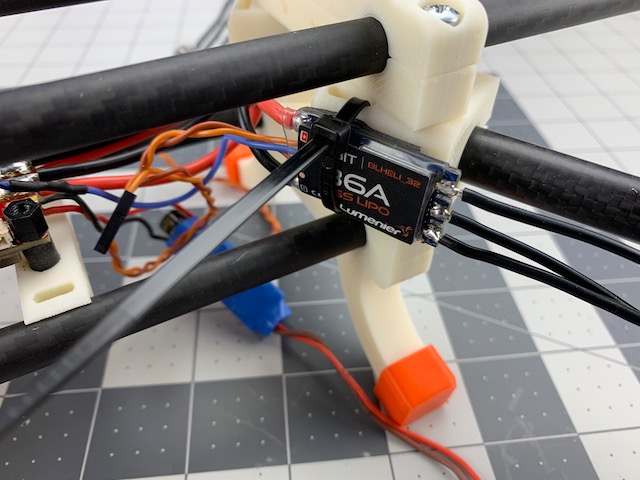
2.4 Install ESC’s
- Time to install ESC’s to inside of Arm Tube Mounts.
- Remember, we are routing wires on outside of arm tubes.
- We used 1.5in/38mm of double sided tape, cut into four equal strips.
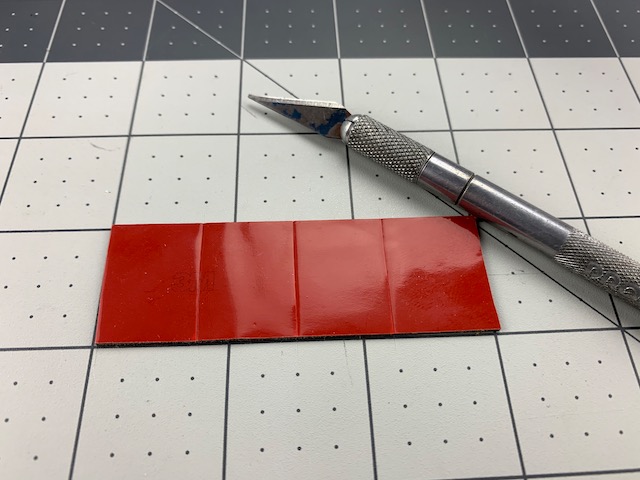
- Apply a strip of double sided tape to the back of an ESC.
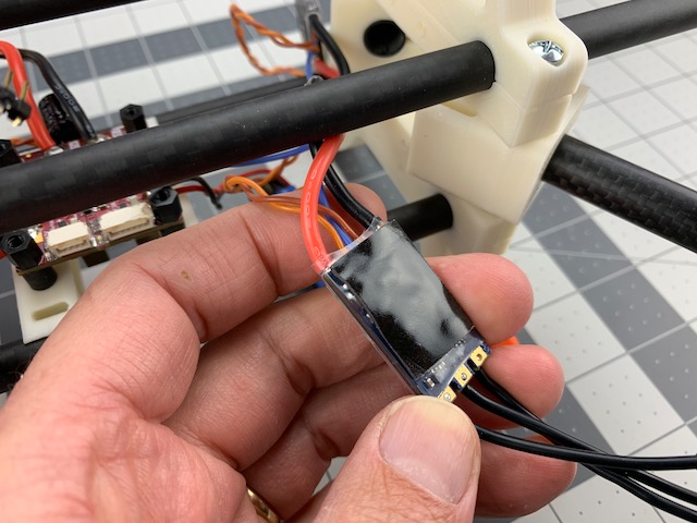
- Stick the ESC to the inside of the Arm Tube Mount.
- See the slot in the Arm Tube Mount? That’s there for the zip tie to hold the ESC in place in case tape fails. Install a zip tie through slot and tighten around ESC.
- Repeat three more times, and don’t forget to trim the zip ties.
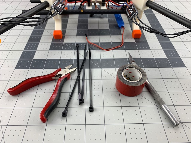
2.5 Secure Motor Wires
-
For this step you could use zip ties or tape. Intent is to secure motor wires that can cause vibrations and/or interfere with props.
-
Zip tie motor wires to arm tube.
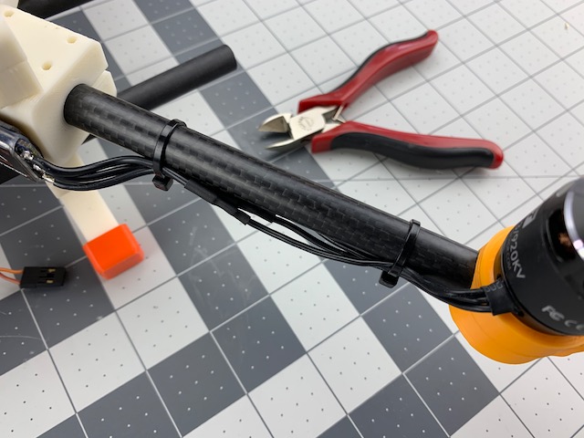
- Repeat until all motor wires are secured to arm tubes.
Power System Complete
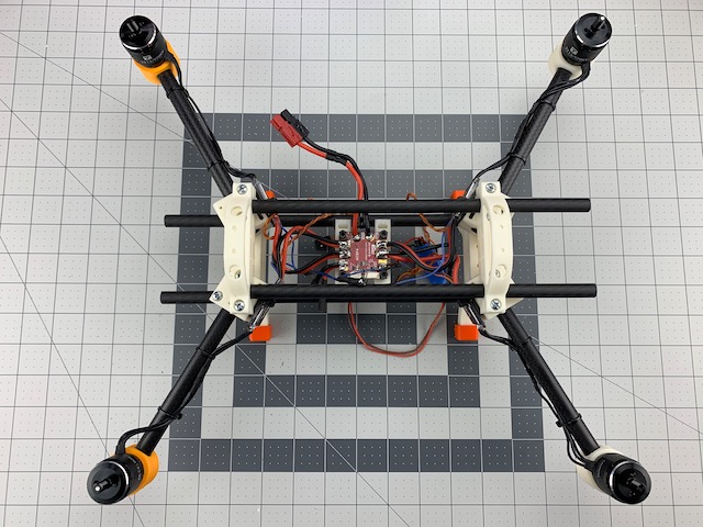
At least the big parts. We will mount the extra BEC and battery in later steps.