ArduPilot Based Setup
CAUTION – DO NOT PROCEED WITH PROPELLORS ATTACHED. We will be energizing the airframe/motors and they pose a risk if left attached to motors.
Bind RX
- Bind the receiver to the transmitter per FrSky instructions. Here is a good guide in case you misplaced the docs that came with your receiver. Just don’t let the BetaFlight specific instructions confuse you.
Load ArduPilot Firmware
- Connect Mission Planner to PixRacer via USB.
- Load latest stable firmware We are using ArduCopter 4.0.3 as of April 2020.
Note – Initial Setup in Mission Planner and the ArduPilot Wiki lists steps under “Mandatory” and others under “Optional” or “Advanced”. Mandatory items in this case refer to calibrations that must be performed to pass pre-arm checks. In this guide we consider each of these steps mandatory for a good flying copter. The general workflow is to start with items listed as mandatory, proceed to optional items, and then finish with advanced items.
Frame Type
Radio Calibration
- Perform Radio Calibration per wiki.
Note - Pitch input might need to be reversed in your radio. Think of pushing the nose/green bar down or pulling the nose/green bar up with the stick.
Serial Ports
Before we proceed we will configure all of our serial ports. We want to make sure the port that the GPS/Compass module is plugged into is properly configured before we go to compass calibrations. Since we are configuring one port we like to do them all. It’s a preference, but we have found it prevents missing an assignment.
PixRacer Serial Ports
| Serial | UART | Protocol | Baud | Options | Notes |
|---|---|---|---|---|---|
| 0 | USB | 2 | 115 | 0 | MavLink v2 |
| 1 | UART2/Telem1 | 9 | 115 | 0 | TFMini |
| 2 | UART3/Telem2 | 2 | 115 | 0 | Companion |
| 3 | UART4/GPS | 5 | 38 | 0 | GPS/Compass |
| 4 | UART8/FrSky | 10 | 57 | 0 | FrSky Telem |
| 5 | UART1/WiFi | 16 | 115 | 0 | ESC Telem |
| 6 | UART7/Debug | -1 | 57 | 0 | Not used |
Note - PixRacer includes a port that supports FrSky telemetry without the need for a convertor. This port is already inverted so there is no need to change port options.
Configure Serial Ports
- Connect Mission Planner to PixRacer via USB.
- Under Mission Planner Config/Tuning Tab go to Full Parameters and Search for “serialx” where x is serial number.
- Update each serial port’s protocol and baud per table above.
- Write parameters.
- Reboot PixRacer.
Accel and Compass
- Calibrate accelerometers per wiki.
- Calibrate compasses per wiki. The default settings should work fine, so just perform a live calibration. The PixRacer has two internal compasses that will act as backup to the primary external compass.
- Reboot PixRacer.
- After reboot reconnect Mission Planner to PixRacer and check Flight Data HUD to ensure the heading works as expected.
Failsafes
- Set and check RC Failsafe per wiki.
Note – We only set the RC failsafe, but you should enable and configure failsafes per your local regulations.
CAUTION – Make sure you understand the actions performed as a result of each failsafe you enable. If a failsafe is triggered, the aircraft will take autonomous actions that may or may not be correct based on your local operating area and/or regulations.
Flight Modes
- Make sure your channel 5 radio switch works as it should to switch Flight Modes.
- Leave all Flight Modes to stabilize for now. We will set them later during Preflight.
Note - Now is a good time to become familiar with the many flight modes available.
Battery Monitor
- Configure the Analog Voltage and Current Monitor
- For the MRo ACSP4 Power Module we use the following settings:
- Monitor: Analog and Voltage
- Sensor: Other
- APM Ver: Pixhawk
- Volt/volt: 13.4545
- Amp/volt: 36.3636
- Reboot the PixRacer
- Plug in your flight battery and check values in Mission Planner.
Note - In order to obtain correct voltage and current values it is important to calibrate your power module. A power analyzer, or similar device, will be required. The video on the wiki shows how to measure current with props reversed. If you use that method please be careful.
Motor and ESC Setup
- You should have your ESC’s plugged into the PixRacer’s PWM output ports from a previous step. Now is a good time to double-check.
- Configure ArduCopter for DShot and BLHeli32 support.
- MOT_PWM_TYPE = 4 = DShot
- SERVO_BLH_AUTO = 1
- SERVO_BLH_POLES = 12 (per your motor specs)
- SERIAL5_PROTOCOL = 16 (ESC telem, but we set it at the start; just check it)
- Reboot the PixRacer
Note - DShot does not require ESC calibration.
Motor Test 1
- NO PROPS INSTALLED.
- Plug in your flight battery.
- Connect Mission Planner to PixRacer via USB.
- In Mission Planner go to Initial Setup » Optional Hardware » Motor Test
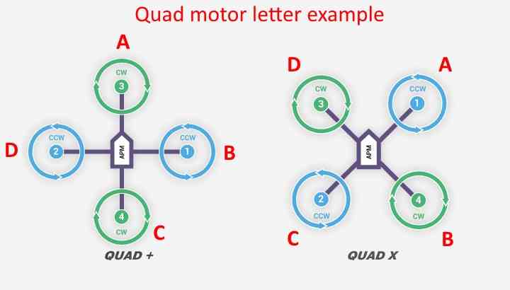
Note - Motor Test assigments A-D ARE NOT THE SAME as the motor 1-4 number assignements. See wiki page for diagrams. Front right first; then move in clockwise fashion.
- Press and hold the Safety Switch until you see solid LED to allow motor arming.
- Test each motor and note rotation per the wiki diagram. We will reverse motor directions as required in next step.
BLHeli
- First disconnect Mission Planner, or anything else using serial ports.
- As of this writing we are using BLHeli32 Suite 32710.
- Follow the video on the wiki to use BLHeli32 Suite to:
- Check ESC firmware settings are all the same.
- Change motor rotations as required.
- Now is also a good time to update ESC firmware. We updated to 32.7 as of this writing.
Motor Test 2
- NO PROPS INSTALLED.
- For this motor test we will make sure the motor rotation is correct and that the radio works to arm the motors.
- Connect your flight battery and wait for tones to complete.
- Press and hold Safety Switch until LED is solid.
- Move throttle stick to bottom right and hold until armed.
- Motors should spin slowly. And in the right directions.
Range Finder (LiDAR)
In this step we will configure the Benewake TFMini LiDAR parameters.
- Configure per the wiki page. Remember, we set the serial ports in a previous step. We are going to be flying outdoors so here are the settings we used:
- RNGFND1_MIN_CM = 30
- RNGFND1_MAX_CM = 600
- RNGFND1_GNDCLEAR = 5
Make sure to verify the results per wiki.
Advanced Configuration
To prepare for our first flights we need to set some Advanced parameters.
Harmonic Notch
The Harmonic Notch Filter is a relatively new addition to ArduCopter which helps filter out vibration noise from IMU sensors in order to provide more predictable control of your copter.
- Configure the Harmonic Notch Filter per the wiki. There is some good information on the wiki page, but most of it does not apply if we use ESC Telemtry, so here are the parameters we used:
- INS_HNTCH_MODE = 3
- INS_HNTCH_REF = 1
Tuning Params
In order to configure the aircraft for first flight we need to set some important PID related parameters:
- Set initial values per the Tuning Process Instructions wiki
- You can infer the numbers from the charts on the Tuning Process wiki page or use this handy spreadsheet.
Logging
Logging in ArduPilot is a very important process that should be well understood in order to properly analyze and troubleshoot performance.
Logging Params
- Our preference is to have a new log saved after each disarm event so we set this parameter:
- LOG_FILE_DSRMROT = 1
- If you need troubleshooting help, please post your data flash logs when posting to ArduPilot Discuss Forum.
- You may need to change your log bitmask depending on what information you need to analyze.
d450 Parameter Files
COMING SOON.
- Link to pre autotune
- Link to post autotune